3D printed parts become a regular feature of familiar objects, from aircraft to digital cameras. Like every other part produced, you can also worn out over time and prone to cracks of pressure and abuse. Whatever the application may be, the lifespan of a 3D printed part is much more difficult to determine, since its production contains new materials and methods. In this article we deal with the science of simulation and prediction of the fatigue life of additive manufacturing designs (AM).
The fatigue life of Ti6
Allin Groom, main scientist at Autodesk Research, is a material scientist. He wrote his doctoral thesis on the lifespan of the parts manufactured. In a previous Autodesk TechX lecture, Broom and Dagmara Szkurlat, Autodesk Research Manager, gave a presentation on the use of generative design to extend the fatigue life of a rotor component for an unmanned aircraft.
In materials science, fatigue is the weakening of a material caused by operating cycles, which leads to cracks and separations. Bridegigam and his team about the typical generative design goals (usually, mass and weight reduction) and his team wanted to optimize the part for life and tolerance of fatigue and fatigue.
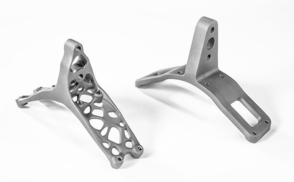
“We knew that we could reduce the mass of the part with a generative design, but we needed a certain number of company cycles. The goal was 300,000 cycles. However, we were able to reach 314,000 cycles,” recalls the groom.
The part was a 3D printed part, which was produced in laser powder fusion (PBF) using Titanium6 (Ti6). The groom and his team had to take into account the anisotropic nature of 3D printed parts, while they explored the design options in the Autodesk fusion. Since 3D-printed parts are produced by layer, the strength of the Z direction tends to be susceptible.
“With some alloys, we knew that we had to treat them differently with the z -orientation in other directions. But this alloy was not particularly sensitive to this. We tested to verify this.” But we were able to show that with Ti6 the surface roughness was not susceptible to cracks. With this knowledge, the manufacturer was able to ignore the usual post -processing requirements such as processing and polishing. “
The attitude of the regulatory authorities of the flight industry towards the parts also develop. “Physical tests replaces all other forms of evidence,” notes Groam. “But the critical nature of the part is also a consideration. A critical aircraft cell component would always require solid evidence, especially if it is made from new materials. For non -critical components, I suspect that simulation would be proven to be acceptable over time.”
The technology on the technology has also achieved maturity that trusts, as the groom sees it. In the early days, many providers and researchers focused on simulating the process themselves in order to gain insights into their reliability. “But we now have a reproducible, repeatable process, so that the focus of the simulation should shift from the creation of the preparation for the performance of the built part,” explains Brütigam.
The Ti6 material used in this project took about 50 years to develop. “This is because we need a good understanding of his thermomechanics to melt it into large sticks that can be treated without cracks and warmth,” says Groom. He believes that AI and machine learning will accelerate the development of new materials.
“The old way of doing things is navigating with a hand -drawn pirate card,” he jokes. “The new way is like the use of Google Maps. We will soon see new alloys that we have never seen before.”
Printed metal against machine metal
Bart van der Schueren, Chief Strategy and Technology Officer, is explained how this differs in metal metal used on the metal used for traditional production. “For example, the 316 L stainless steel, which you can preserve in large quantities, is not the same as the 316 L, which is used in 3D printing,” he says. “We recognized this. That is why we have collected the mechanical properties of the parts we have made over the years. We now know the mean for the tensile strength of these materials.”
However, the average is simply the base line. So that parts can be used in general applications in which the failure does not live and limbs (e.g. a button on a DSLR camera), a tensile strength is normally acceptable. In contrast, for parts that are used in critical applications (e.g. aircraft parts for the start and landing) should be higher than the mean. “To determine, you have to know the Gaußsche distribution around the average. We have this information available in our manufacturing units,” says van der Schueren.
What happens to metal in the process is relatively easy to simulate compared to polymer and plastic, as van der Schueren states. “With Metal AM it is essentially a welding process in which you stack the layers and let them cool,” he explains. “For polyamide or plastic materials, first heat it near the melting point, the properties of the materials change. Then there is a recrystallization process during the cooling process that changes the material again. This process can begin a few minutes after cooling your printed part. This is extremely difficult to simulate.
Chris Robinson, Senior Product Manager for Additive Manufacturing, ANSYS, states in a similar way: “Simulation of metal AM is much easier, but there is a wide range of glass crossing temperatures in the fusion filament production (FFF) with plastic and polymers.
The more advanced use of AM to predict and simulate the failure of 3D printed parts can include the assignment of various properties to different regions of the part in order to better reflect the thermal history of the part. “While the microstructure of decorated materials is quite consistent, due to their thermal anamnesis, changes are passed on the materials. With Ansys mechanically, based on the thermal profile of a part, you can identify regions with more pores.” You can also add CT scandates or in -situ measurement data to your model. “
Frequently used on the materials are already part of the ANSYS software and are ready to select from a library. “We tested and validated a lot to develop these material models,” says Robinson. “You can also access the Granta material models that have a different level of depth and data. Of course we also see that new materials are developed and introduced every day. So if you have empirical data from a test house, you can also enter it.”
In 2018, Ansys and Granta, a spinoff from the Department of Engineering at the University of Cambridge, joined collaborative commitment. A year later, in 2019, Ansys Grante took over and enabled him to include the latter data in his software packages.